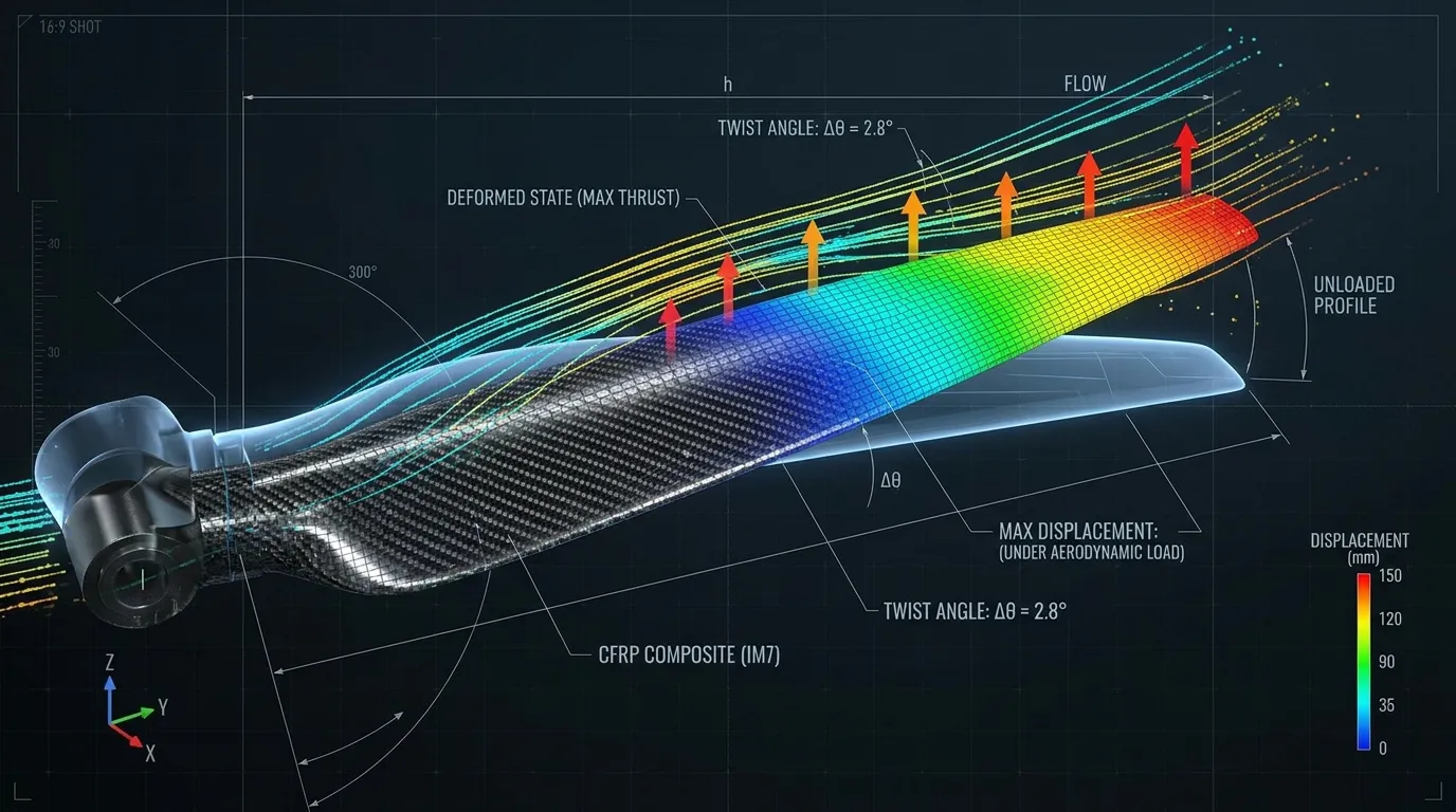
The unloaded geometry is only the starting point
In propeller design, the chord, airfoil and twist distribution are chosen for specific operating conditions. But a real blade bends and twists under load. This change in shape can affect the angle each section makes with the flow and the load distribution. It should therefore not be assumed that the geometry in the design file stays the same in operation.
The significance of deformation depends on where and in which direction it occurs as much as on its magnitude. A change near the tip and a local change of shape at the root do not have the same effect. The evaluation should cover the whole propeller and the RPM range in which it works with the motor.
Bending and twisting are different requirements
Bending relates to the blade's displacement in the direction of the load; twisting relates to the rotation of sections along the blade. A structure that is stiff in bending may not have the same torsional stiffness. That is why a single deflection value does not explain the whole behavior.
Twisting can increase or reduce the aerodynamic load by changing the local blade angle. This effect is not always in the same direction. Geometry, the center of load and structural properties are decisive together. Controlled deformation can be part of the design, but flexibility whose outcome has not been predicted makes performance and load estimates uncertain.
The laminate structure shapes operating behavior
The properties of carbon fiber are used in the blade through fiber orientations and placement. Plies carrying longitudinal load, plies contributing to shear and torsion, and local reinforcements are designed together. A propeller's stiffness cannot be judged by looking at the carbon weave on its surface.
The ply layout can also change certain bending–twisting couplings. If this behavior is to be used deliberately, it should be verified by analysis and testing. Adding a ply at random can change both weight and load distribution. The stiffness target should be considered together with strength, fatigue and manufacturability.
The root transfers the load of the whole blade
Besides continuing the aerodynamic shape, the blade root is a structural connection zone. Centrifugal effects, bending and torque generated during rotation are transferred to the hub here. Holes, inserts and geometric transitions are natural parts of this load transfer.
Thickening the wide part of the blade does not on its own fix a weak root connection. Mating surfaces, clamping conditions and ply continuity should be evaluated separately. A small movement at the root can affect the position of the entire blade. That is why mounting conditions must be repeatable when deformation is measured.
Analysis and testing complement each other
Structural analysis produces results from geometry, material data, ply layout, boundary conditions and loads. If the inputs are not defined correctly, even a detailed model can predict the wrong behavior. In particular, the real connection stiffness and production deviations should be included in the evaluation.
Measuring the unloaded geometry, tracking deflection and twist under controlled load, and then rotating tests suited to the project answer different questions. Vibration and natural frequencies can also be examined for dynamic behavior. Because rotation can change the structure's behavior, a measurement on a stationary blade should not be assumed to represent the full RPM range.
At Tulkas, a propeller is a laminate and a system component
Tulkas evaluates a propeller not only by its outer form but also by its material, ply structure, root connection and production method. Measurements from prototypes are used to determine the revisions needed. The test scope is built for each project based on target RPM, thrust and operating conditions.
Frequently Asked Questions
Is a stiffer propeller always more efficient?
No. Stiffness can help control the operating geometry, but efficiency also depends on geometry, surface, RPM and motor matching. The goal is not maximum stiffness in every direction, but behavior that suits the mission and has been verified.
Do two carbon propellers of the same weight flex the same way?
No. Fiber orientations, section distribution, resin and internal structure can differ. Even with the same mass, bending and torsional stiffness can vary. Comparisons should be made with controlled mounting and common load conditions.
Does a deflection test on a stationary blade show flight behavior?
It provides useful initial data, but it does not represent all of the rotational and real flow conditions. Operating RPM, aerodynamic load distribution and dynamic effects should be evaluated separately. A single test does not cover every verification need.
Can an existing propeller be improved by adding carbon plies?
An extra ply changes mass, balance, geometry and stiffness. Uncontrolled application is therefore not suitable. Development should be carried out through a defined design revision and a new production and test plan.
Let's develop a propeller for your operating conditions
Share your target RPM, thrust, motor and mounting information with Tulkas. Let's address aerodynamic geometry and structural behavior together in the same development process.