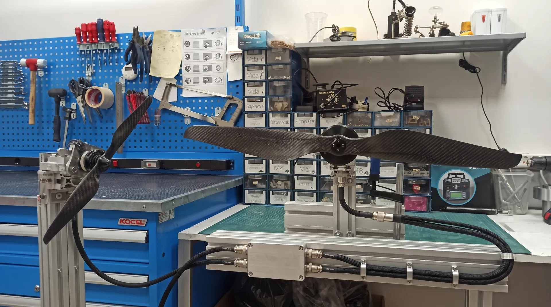
Noise and vibration are not the same problem
On a UAV, high sound and high vibration are often observed together but may not come from the same root cause. Noise arises from the blade's interaction with the air, blade passage frequency, tip vortices, turbulence and motor electromagnetic noise. Vibration, on the other hand, can grow from mass imbalance, geometric deviation, motor bearing condition, mounting stiffness, resonance and time-varying blade loads.
This distinction matters. It is not possible to solve aerodynamic noise simply by balancing, or to eliminate vibration caused by a loose motor mount simply by changing the tip geometry. The sources must first be separated.
Blade tip speed and acoustic signature
The tip of the propeller blade moves at a much higher circumferential speed than the root. As RPM and diameter increase, tip speed rises; pressure fluctuations and high-frequency sound components can become more pronounced. Simply lowering RPM may not be enough to reduce noise, because the diameter, blade area or blade count must be reconfigured to maintain the required thrust.
Trying to produce the same thrust at a lower tip speed requires system-level optimization. The motor's torque capacity, airframe clearance and mission speed constrain this decision.
Tip geometry, load distribution and vortices
The flow that moves from the pressure surface to the suction surface at the blade tip forms the tip vortex. Tip loading, profile selection, sweep and tip shape affect the character of the vortex. A sharply or arbitrarily shaped tip design, even if it eases manufacturing, can give an undesirable result in terms of acoustics and efficiency.
For noise reduction, distributing the load more evenly along the blade, reducing excessive loading at the tip region, and preserving surface quality are important. However, tip geometry cannot be determined with the same recipe for every platform.
Static and dynamic balance
Static balance checks the alignment of the propeller's center of gravity with the rotation axis. Dynamic balance addresses the imbalance and moment created by the rotating part across different planes. Static balance alone may not be sufficient, especially on large-diameter, multi-bladed propellers or ones with a complex hub structure.
A balance problem can increase motor bearing loads, corrupt sensor data, cause vibration in camera footage, and accelerate fatigue at mounting regions. Balancing is not a cosmetic step done at the end of production — it is part of production repeatability and quality control.
Geometric repeatability and blade matching
Even if two blades have the same mass, if their chord, twist or profile deviate, each produces a different aerodynamic load every revolution. This can lead to periodic vibration that doesn't show up on a balancing rig but appears during operation.
Mold accuracy, ply placement, resin distribution, cure and finishing processes all affect blade geometry. For this reason, mass matching must be accompanied by geometric measurement and critical cross-section control.
Stiffness and aeroelastic behavior
A propeller bends and twists under load. This deformation changes the blade angle and can cause the load to fluctuate over the course of a revolution. If carbon fiber ply orientation or plastic material stiffness is not chosen correctly, the propeller will not operate with the geometry it was designed with.
Sometimes controlled flexibility can be advantageous under impact or load changes, but this behavior must be intentional. The goal is not the stiffest blade under all conditions, but the blade that maintains a stable and safe geometry under the operating condition.
The effect of motor, airframe and control system
A propeller that runs smoothly on its own on a test bench can still generate vibration once mounted on the platform. Motor mounting surface, arm stiffness, connecting bolts, bearing condition, ESC commutation and the control loop can amplify vibration. On multi-rotor platforms, propellers interfering with each other's flow also increases load fluctuations.
This is why troubleshooting should measure the system rather than blaming the propeller, motor or airframe separately. RPM sweeps, vibration spectra at different throttle levels, and mounting-point measurements can reveal resonance regions.
Tulkas' test-driven approach
In propeller development, Tulkas treats balance, noise, vibration and structural behavior as being monitored together with thrust and power values. In an existing propeller, the source of a problem could be manufacturing deviation, geometry, material or integration.
Based on the measurement results, blade geometry, ply layup, hub connection or production control is revised. The goal is not just a quieter propeller, but a repeatable thrust solution that is compatible with the platform's sensor, motor and airframe systems.
Frequently Asked Questions
Why does a balanced propeller still vibrate?
Even if the mass balance is correct, the blade geometries, stiffnesses or aerodynamic loads may not be equal. Motor, mounting and airframe resonance can also cause vibration.
Does adding more blades reduce noise?
Under some conditions it can allow lower RPM and a more balanced load distribution, but it changes the blade passage frequency and profile drag. A system-level evaluation is required.
Does minor surface damage on a propeller matter?
Damage, especially at the leading edge and blade tip, can affect load distribution, noise and balance. The size and location of the damage must be technically evaluated.
Conclusion
Share your propeller, motor and platform data with Tulkas to solve noise or vibration issues through measurement rather than guesswork.