Define the goal of the conversion first
The reason for moving to composite may be to reduce weight, manage corrosion, lower the part count or gain stiffness in a particular direction. These goals are not always achieved with the same design. The first step is to define clearly which problem is to be solved and against which criteria success will be judged.
Not only the weight of the existing metal part, but also its assembly function, loads, temperature, impact, maintenance and production volume are starting data. The targeted gain may come with a more complex mold, a different connection or a new verification need. The conversion decision should be made on the whole of these effects.
Metal geometry may not use the strengths of composites
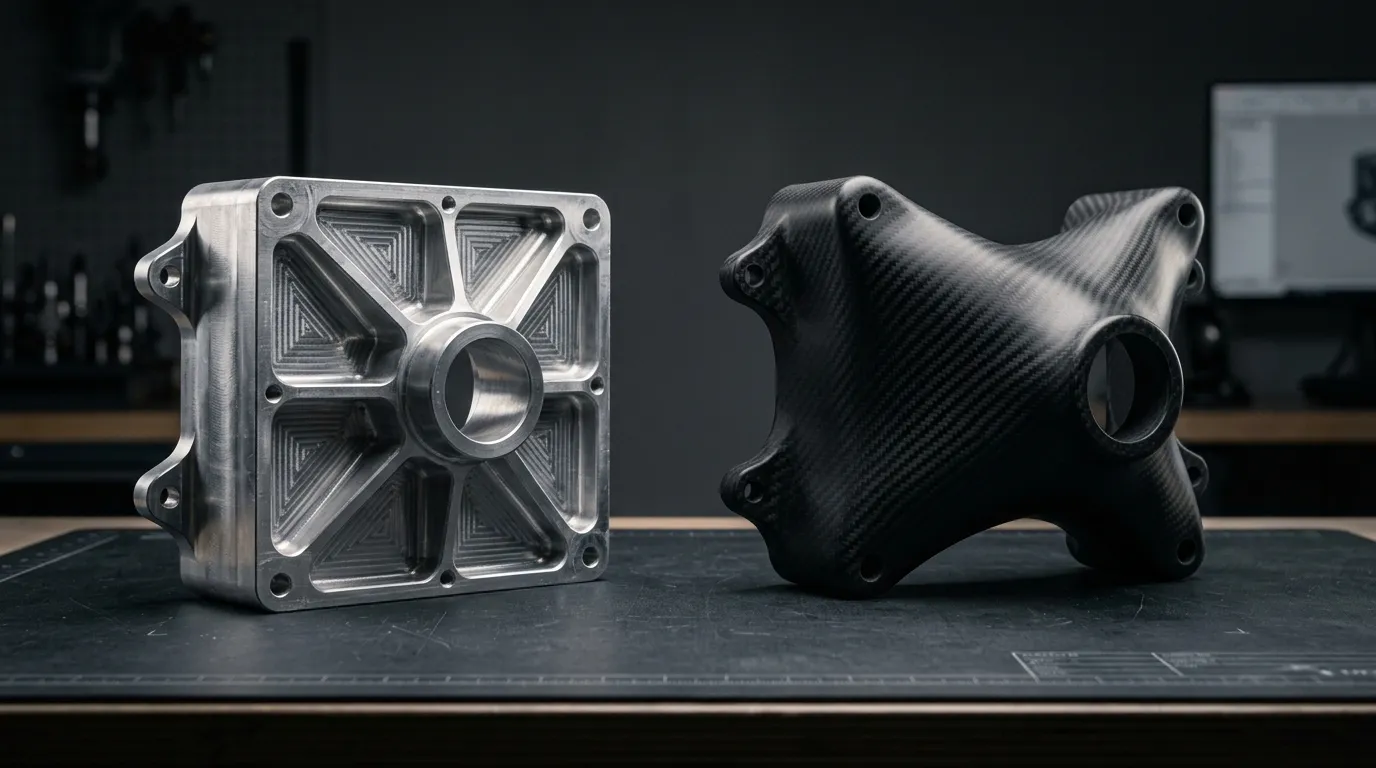
Metal parts are often designed to suit machining, casting or welded fabrication. Thin ribs, deep pockets, small radii and local bosses can be functional in these methods. The same details can make fiber placement or demolding difficult in a composite.
In composite design, surfaces along which plies can run continuously, suitable transitions and accessible mold layouts are evaluated. Some areas can be reorganized as a shell or sandwich structure. The aim is to meet the same function with a manufacturable structure rather than preserve every detail of the metal model.
Load paths are translated into fiber orientations
The directional properties of composites require knowing in which directions the loads are carried. A dominant unidirectional load, multi-axial connection loads and impact do not create the same laminate need. The ply structure is defined through strength, stiffness and damage behavior.
A single tensile strength on a material data sheet does not show that the finished part is suitable. Holes, thickness transitions, connections and environmental effects are also evaluated. Not every assumption of the calculation approach used for metal should be carried directly over to composites. Design and verification should represent the chosen material system.
Connections and system interfaces are reconsidered
A tapped thread or welded joint in a metal part may need a different solution in a composite. Insert, bonding, bolting or hybrid joint options are examined according to assembly and maintenance requirements. Spreading the load over a wide area and preventing local crushing are important.
The electrical conductivity of carbon composite and its contact with metal parts should also be evaluated at system level. Requirements such as electrical insulation, grounding, antenna placement or galvanic compatibility may become important depending on the project. A change of material affects not only the mechanical model but also other system interfaces.
Part consolidation and total cost
Combining several metal components into a single composite structure can reduce assembly steps and some connections. On the other hand, it may require a larger mold, more complex production or replacing a larger part after damage. It should not be assumed that reducing the part count always brings a cost advantage.
The comparison should be made at the finished assembly level. Material, tooling, labor, quality control, assembly and service costs are taken into account. A simple low-volume metal part may still be the better option. The advantage of composite appears when it meaningfully meets a specific weight or performance requirement of the project.
Prototype verification should represent real use
Correct dimensions on the first prototype do not show that the conversion is complete. Critical requirements such as deformation under load, connections, impact or environmental conditions should be verified. The test plan should speak the same language as the design goals.
When moving to series production, the ply definition, material records, mold and inspection methods are also fixed. Moving from metal to composite is as much about reproducing the same result repeatedly as about getting one good sample. Tracking changes through revisions makes later performance evaluation easier.
Conversion feasibility with Tulkas
Tulkas evaluates the existing part in terms of geometry, loads, material and production method together. Design development, tooling, prototype and repeat production requirements are handled in the same process. The goal is to identify where composite delivers technical or economic value and turn that into a verifiable development plan.
Frequently Asked Questions
Can every aluminum part be replaced with carbon fiber?
A meaningful conversion should not be expected for every part. Temperature, impact, connections, maintenance and cost can be decisive. Suitability is evaluated through the part's mission requirements rather than the general properties of the material.
Can the same thickness as the metal part be used?
Such an assumption should not be made directly. The directional properties and ply layout of a composite are different. A different section, local reinforcement or sandwich structure may be needed for the same function. Thickness is determined as a result of the design.
Can the weight saving be given as a percentage from the start?
An estimate can be made in a preliminary feasibility study, but a reliable figure is determined by the finished assembly definition. Inserts, connections, coatings and local reinforcements are included in the total mass. A common saving percentage should not be quoted for every part without verification.
Is an existing CAD file enough to start development?
It is an important start, but loads, interfaces, the operating environment and goals are also needed. CAD geometry alone does not explain under which conditions and why the part works. Existing test results and issue records strengthen the evaluation.
Let's examine the conversion potential of your existing part
Share the CAD model, weight, function, loads and production volume of your metal part with Tulkas. Let's evaluate together the technical and production value of moving to composite.