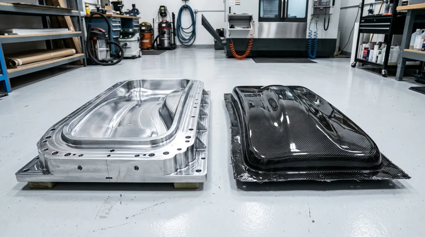
A mold is more than the inverse geometry of the part
Creating a clean mold surface from the digital model is an important step, but on its own it is not enough for production. The mold should be suitable for fiber placement, for the pressure and temperature required during processing, and for demolding and measuring the part. Flanges, the parting line, fixtures and handling arrangements support these functions.
Before designing the mold, it should be decided which method will produce the part and which of its surfaces are critical. A quickly changeable solution may be enough for a prototype, while maintenance, cycle time and dimensional repeatability matter more in series production. It is not correct to assume the same tooling investment for every project.
In aluminum tooling, thermal behavior and machining go together
Aluminum molds can offer several advantages in machinability, surface generation and heat conduction. However, the size and geometry of the part and the required wall thickness affect mold mass and cost. The heating method and support arrangement also play a role in how temperature is distributed across the mold.
A metal mold and a carbon laminate do not share the same thermal expansion behavior. When cooling from the cure temperature, this difference can cause dimensional change or difficulty in demolding. For high-precision work, machining the room-temperature CAD dimensions alone may not be enough; process conditions and first-article results are evaluated together.
In composite tooling, the material system is decisive
Composite molds can be a functional production option within a suitable part and volume range. The mold's structural laminate, surface layer, reinforcements and resin system should be designed together. Resistance to the curing temperature to be used and behavior under repeated thermal cycles are important in material selection.
Using a carbon-reinforced mold does not automatically give the same expansion behavior as the part. The ply layout and resin also affect the result. The mold must hold its shape under vacuum, must not leak air through its joints and its surface must withstand repeated release cycles. A large mold without adequate support can distort in production even if it was machined correctly.
The parting line and access determine production time
The direction in which the part will be removed from the mold should be resolved at the design stage. Undercuts, thin edges and enclosed volumes may require a multi-piece mold. Each additional mold piece, however, can increase the need for alignment, sealing and maintenance. The goal is not a mold with the fewest pieces, but controlled and repeatable production.
The area where the operator can place the fabric, access to corners and securing of inserts should also be evaluated. A geometry that looks manufacturable on screen can produce wrinkles or gaps during ply placement. Reviewing the mold design and lamination plan together brings these problems to light early.
Look at total production cost instead of the initial investment
A low-cost mold can raise total cost if it requires intensive surface rework or frequent maintenance. A higher initial investment only makes sense with the expected volume and cycle savings. Rather than giving a single number for tool life, the material, temperature, release method and maintenance conditions should be explained.
First articles test the mold's production use as well as its dimensional accuracy. Demolding time, marks at mold joints, critical sections and weight repeatability should be observed. The decision to move to series production is made on the basis of this feedback.
Tulkas's approach to tooling
Tulkas evaluates tooling and mold requirements according to the part's production method and repeat scenario. Reference surfaces, mold closure, part positioning and the process sequence are addressed within the technical scope. The aim is to create a mold arrangement that carries the design geometry and also supports the production flow.
Frequently Asked Questions
Is a composite mold always cheaper than a metal mold?
No. Size, surface, temperature, master pattern, reinforcement and target life change the cost. The comparison should not be based only on the purchase price of the mold; maintenance, cycle time and the expected number of parts should also be considered.
Can series production continue with a prototype mold?
It may be possible in some low-volume projects. However, dimensional stability, surface life and cycle time must suit the target production. A successful first article does not on its own prove suitability for long-term repetition.
Should the mold dimensions be the same as the part's CAD dimensions?
That depends on the material and process. Thermal expansion, curing effects and changes that occur during cooling are evaluated. Any required dimensional corrections should be determined from analysis and sample results, not by applying a generic factor at random.
Can tool life be stated precisely at the outset?
It is not correct to state an exact life without knowing the operating conditions. Material, thermal cycles, maintenance and the demolding method affect tool life. The target number of repetitions is defined in the technical scope and tracked with usage data.
Let's plan your tooling investment around your production goal
Share your part model, production method, target quantity and critical surfaces with Tulkas. Let's define the tooling approach together based on your prototype needs and repeat production expectations.