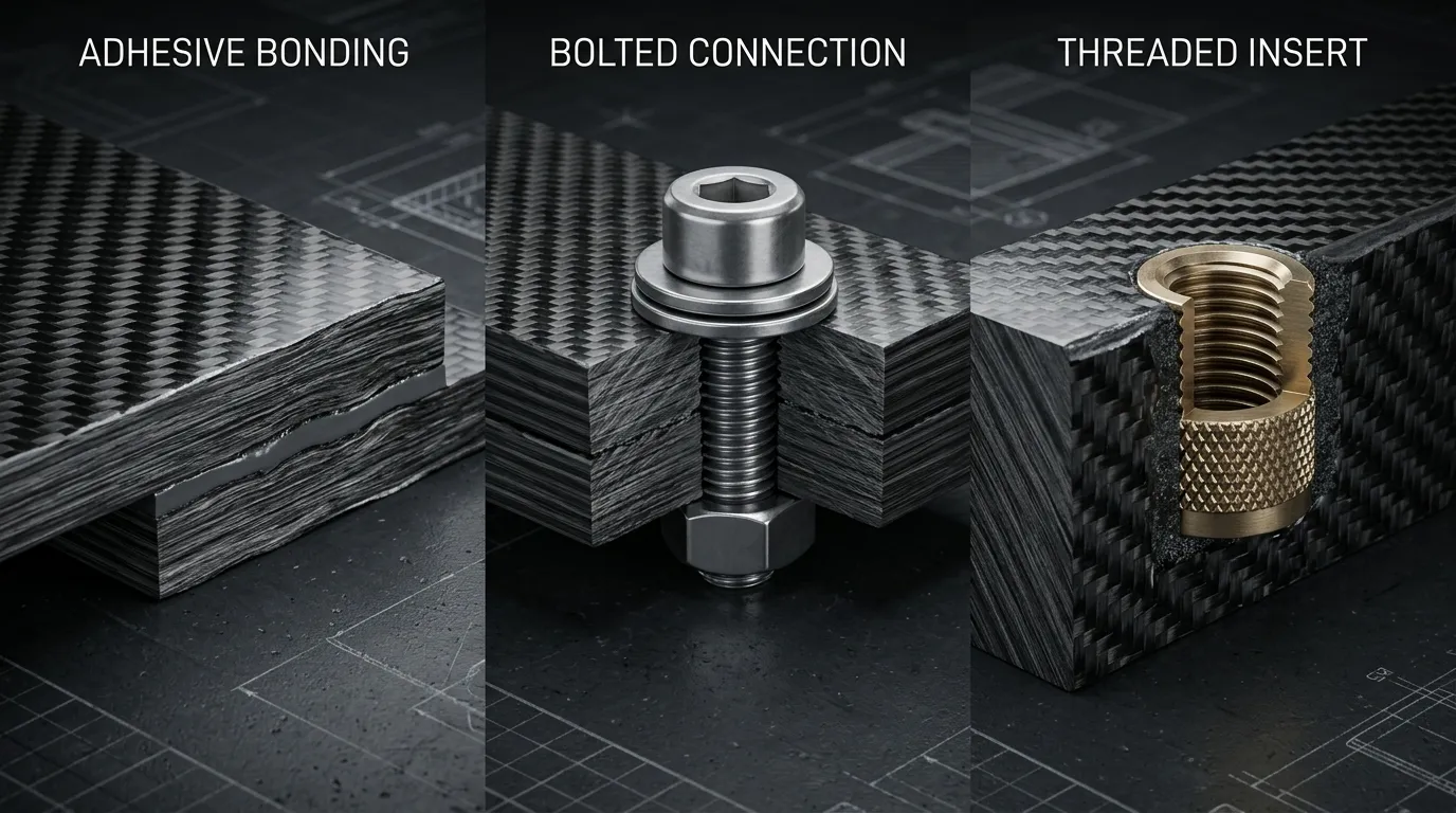
Joint design starts by following the load
A carbon arm or panel may be strong enough, but if the area that transfers the load into the airframe is not suitable, the part cannot do its job. A joint places many functions on a small area: force transfer, positioning, clamping, sealing and sometimes the ability to be disassembled.
First, the direction and magnitude of the transferred load should be defined. Tension, shear, bending and cyclic loads can all exist in the same joint. Then assembly access, environmental conditions and maintenance needs are evaluated. Carrying a joint from a metal part over to a composite with the same dimensions can overlook the material's directional behavior.
Bonding can spread the load over a surface
A bonded joint, when properly designed, can transfer the load over a wider area. For this, overlap length, the adhesive layer, part stiffnesses and load direction should be considered together. Increasing the bond area can be helpful, but because of the stresses that form at the ends, load capacity does not always rise in proportion to area.
Surface preparation is an inseparable part of the joint. The surface must be clean, suitably roughened and compatible with the adhesive to be used. Coating or release agent residues can harm the joint. Application temperature, mixing, working time and curing conditions are planned according to the product's technical data. Clamping the parts harder brings no advantage if it does not preserve a suitable bondline thickness.
In bolted joints, local failure modes are examined
A bolt offers disassembly and ease of assembly, but the drilled hole interrupts fiber continuity. Bearing pressure around the hole, shear-out toward the edge, net-section weakening and delamination should be evaluated. There is no single rule for hole diameter and edge distance that applies to every laminate.
Clamping force should also be controlled. Excessive force can crush the laminate or a sandwich core; insufficient force can lead to slipping and loosening. Washers, bushings and load-spreading parts can help, but their size and contact surface are design requirements. It is not correct to apply a generic metal joint torque directly to a composite.
An insert is designed for load transfer
Metal inserts can be used to create a threaded connection, make assembly repeatable or transfer load into the composite. The insert's outer geometry, embedment area, surface preparation and surrounding reinforcement work together. Rotation, pull-out and the possibility of local damage around the insert should be examined.
In sandwich structures, the area around an insert may need to be supported with suitable potting or a load-carrying zone. Environmental compatibility between metal and carbon is also important. In conditions with moisture and electrolytes, galvanic interaction is evaluated, and the necessary electrical insulation and sealing details are included in the design.
Hybrid joints and verification
Adhesive and bolts can be used in the same joint, but simply adding the capacities of the two methods is not correct. Which component carries the load at which stage, the stiffnesses and joint clearances determine the result. The bolt's role in positioning, assembly or as a backup load path should be clearly defined.
Joint verification should not consist only of pulling a clean coupon. Real assembly tolerances, temperature and humidity conditions, disassembly needs and cyclic loads should be reflected in the test plan. Small coupon results are useful, but separate verification of the load path in the real part may also be needed.
Tulkas does not treat the joint separately from the part
In composite part development, Tulkas handles geometry, laminate and interfaces together. The joining method is selected based on loads, production, assembly and maintenance requirements. Sharing the dimensions of the mating part and the assembly conditions during the technical review makes it easier to develop a solution that suits the real operating situation.
Frequently Asked Questions
Is bonding stronger than bolting?
A general ranking is not correct. Load direction, surface area, material, environment and maintenance requirements determine the result. The two methods should be compared against the same task and acceptance criteria and, where necessary, evaluated together.
Is a thicker layer of adhesive always better?
No. The suitable bondline thickness depends on the type of adhesive, gaps and joint design. Too much or too little thickness can cause adverse behavior. Application should be controlled with technical data and a validated process.
Can a metal insert be in direct contact with carbon?
That decision depends on the type of metal and the operating environment. Galvanic interaction should be evaluated, especially in wet or salty conditions. Measures such as an insulating layer, a suitable adhesive and sealing are defined for each project.
Can the same joint be assembled and disassembled repeatedly?
If repeated maintenance is defined in the design, a suitable solution can be developed. Threads, the area around the insert, clamping conditions and surface wear should be evaluated. A joint that works at first assembly is not assumed to have unlimited assembly–disassembly life.
Share your joint conditions
Share the composite part, the mating part, the loads and your maintenance expectations with Tulkas. Let's evaluate bonding, bolting and insert options together with production and assembly requirements.