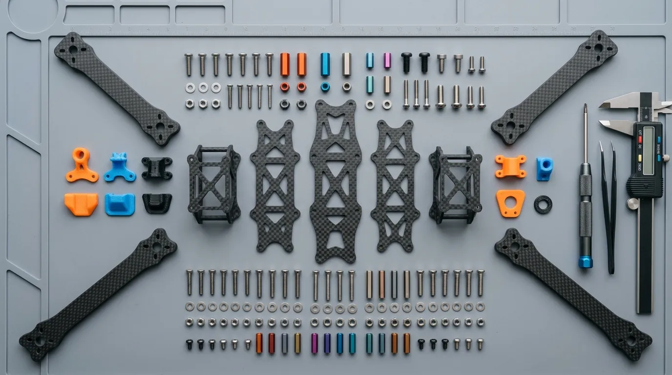
Define the use case first
A racing drone and an industrial imaging platform do not share the same frame priorities. In racing, agility and low mass come first, while freestyle use puts more weight on repeated crashes and part replacement. In industrial applications, payload, camera view, cable routing and mission time can be more decisive.
That is why frame design should not start from propeller size alone. Motor and battery mass, flight weight, equipment to be carried, mounting dimensions and maintenance expectations should also be defined. Within the same outer dimensions, different missions may need different arm sections and connection layouts.
Arm geometry and carbon structure work together
The length, width and thickness of the motor arm and the way it attaches to the center frame affect its behavior under load. As an arm gets longer, the bending moment at the root increases under the same tip load. A narrow root section or an abrupt change in geometry can concentrate the load in a small area.
The ply orientations of the carbon plate are part of this geometry as well. Changing an arm's orientation on the plate during CNC cutting can change where the fibers sit relative to the load direction. Cutting the outline correctly is not enough; the properties of the laminate used and the part nesting should also be defined.
There is no single fix for stiffness and vibration
Motors and propellers transmit excitation to the frame at different frequencies. How this excitation relates to the frame's natural vibration behavior can affect flight controller readings, the camera and the connections. A stiffer frame can reduce some problems, but not every vibration issue originates in the frame.
Propeller damage, a motor bearing, a loose connection or incorrect assembly can produce similar symptoms. The evaluation should be based on measurements taken at different motor speeds. Just as flight controller filters do not fix a mechanical fault, randomly added soft mounts can increase unwanted movement of the electronics. Mechanical design and control tuning should complement each other.
Managing damage matters as much as impact resistance
After a crash, a carbon part may show little visible damage on the outside while its plies are damaged inside. Do not conclude that an arm is fit to fly just by looking at it. Inspection and replacement criteria should be set according to the operating conditions.
A replaceable arm design can make maintenance easier. On the other hand, extra joints should be evaluated for weight, loosening and local load transfer. A one-piece frame may have fewer joints but can require replacing a larger section after minor damage. The right solution depends on the expected crash frequency and maintenance routine.
Electronics and assembly layout are part of the flight
Battery position affects the center of gravity, camera position affects the field of view, and the spacing between motors affects propeller placement. Cables should be protected from rubbing on sharp carbon edges, and unwanted contact between electronics and conductive carbon surfaces should be prevented. Antenna placement should also be verified with the effect of the carbon structure in mind.
Screw lengths, motor mounting surfaces and assembly access should be checked during design. If all the electronics must be removed to disassemble it, the practical advantage of a quick-swap arm shrinks. Trying the maintenance steps on the assembly model gives valuable feedback before production.
A mission-ready FPV frame with Tulkas
Tulkas produces CNC-cut carbon fiber frame parts for racing, freestyle and industrial FPV platforms. Geometry and plate selection are evaluated together with weight, impact behavior, vibration and assembly requirements. For a custom design, sharing the use case along with part dimensions makes it easier to produce a frame that matches the real need.
Frequently Asked Questions
Is a thicker carbon arm always better?
No. Thickness can increase stiffness, but it also changes mass and the loads transferred to other parts. Do not decide on thickness alone without looking at arm length, width, laminate structure and the center connection together.
Does camera vibration always come from the frame?
Not always. The propeller, motor, connections and camera mount can also be the source. The problem should be isolated by measuring at which speeds it appears and in which part it starts. Replacing the frame alone does not guarantee a fix.
Can an arm be used after a crash if there is no visible crack?
The absence of a visible crack does not prove there is no internal damage. The severity of the impact, the condition of the connections and any change in stiffness should be evaluated. The return-to-flight decision should follow the inspection and replacement criteria of the manufacturer or the project lead.
What information is needed for a custom FPV frame?
Motor and propeller sizes, target flight weight, battery, electronics mounting holes, camera placement and the use case are the key inputs. An existing CAD file or reference frame makes the development process easier.
Let's evaluate your platform's frame together
Share your motor, propeller, electronics layout and target weight with Tulkas. Let's work through the carbon plate and frame geometry together based on your flight, assembly and maintenance needs.