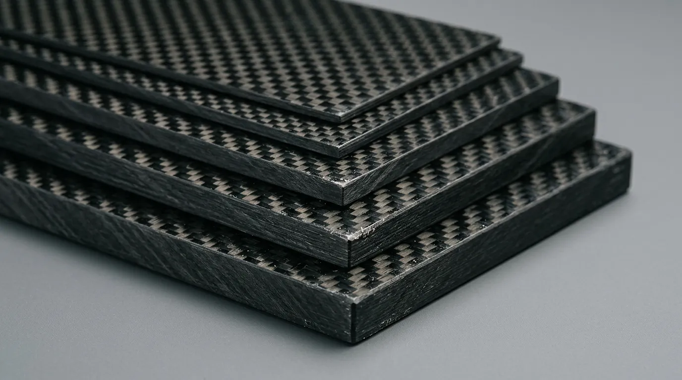
Why do plates of the same thickness behave differently?
When carbon fiber is chosen for a UAV mounting plate, an electronics carrier or a machine bracket, the first question is usually thickness. Yet two plates with the same outer dimensions can show different stiffness and strength because of fiber type, resin system, ply sequence and production quality. Even if they look alike, one may not be a direct replacement for the other.
Selection should start with the function of the part. The load application points, the distance between supports, the allowable deflection and the fastening layout should be defined. Carrying a load without breaking and flexing little enough in service are different requirements. On a precision sensor carrier, too much flex can compromise function even when strength is sufficient.
The visible weave does not describe the whole internal structure
The plain or twill weave seen on the surface tells you about the outer ply of the laminate. Inside there may be repeats of the same fabric, unidirectional plies or a structure made of different fibers. That is why choosing a structural plate from a surface photo alone is not correct.
Terms such as 3K used for carbon fabrics indicate the number of filaments in a fiber tow. On its own, it does not show the strength class of the material or the load capacity of the finished plate. A technical evaluation should consider fiber grade, fabric weight, resin and laminate structure together. A decorative carbon veneer and a laminate made to carry load also serve different purposes.
Ply orientations determine the path the load follows
Fiber direction is one of the key variables that determine which load directions a composite will resist most effectively. A part dominated by tension and bending along one axis and a plate carrying in-plane loads in several directions may not need the same ply layout.
Balanced and symmetric laminate layouts can be used to reduce some unwanted bending and twisting couplings. Even so, loads and manufacturing conditions should be evaluated instead of applying one standard sequence to every project. Rotating a part on the plate in the CNC nesting plan can also change the fiber direction relative to the part's load axis. A nesting layout that reduces material waste is not suitable if it compromises the mechanical requirement.
Thickness is chosen together with connection and machining requirements
In most cases, bending stiffness rises as thickness increases; but weight, material consumption and machining time also go up. Increasing thickness alone does not fix a poorly placed hole or an inadequate connection area. Sometimes a more efficient solution comes from changing the part's shape, the support span or a local reinforcement.
Holes and cut edges change the continuous fiber structure. Bearing damage around holes, tear-out toward edges and delamination should be evaluated. Countersinking can also remove a significant share of the load-carrying plies in a thin plate. The fastening solution, the position of holes to be drilled later and the assembly load should be defined at the design stage.
What information should an order include?
Besides plate dimensions, the thickness tolerance, flatness, surface expectation and end use should be defined. The drawing of the part to be machined, its critical holes and orientation information should also be shared with the manufacturer. A glossy surface requirement and a bondable surface requirement are not the same; surface preparation is planned with the subsequent operations in mind.
In series use, the suitability of the first sample alone is not enough. The material and production definition must be repeatable. Approved properties should be clearly documented so that the part's behavior does not change when the supplied plate changes.
How does Tulkas approach carbon fiber plates?
Tulkas evaluates a carbon fiber plate requirement together with the part's application and production needs. Different thickness and weave options are selected based on CNC cutting, assembly, surface and structural expectations. The goal is not just to supply a sheet of the right size, but to establish the right plate definition for your project.
Frequently Asked Questions
Is a 3K carbon plate always stronger?
No. The term 3K describes the number of filaments in a fiber tow. The strength of the finished plate depends on fiber properties, resin, ply orientations, fiber volume fraction and production quality. Products should not be compared on this term alone.
Does using a thicker plate solve every problem?
Thickness helps in some load cases, but it does not on its own fix problems caused by connections, ply orientation or geometry. First identify which requirement is not being met, then evaluate thickness and design together.
Does a carbon plate have the same properties in every direction?
That depends on the laminate structure. Some laminates are arranged to behave similarly in different in-plane directions. Even so, through-thickness properties are not the same; metal-like behavior in all directions should not be assumed.
Can I get a quote by giving dimensions only?
For a standard plate, dimensions and quantity are a starting point. For a structural or special application, the use case, loads, surface expectation and machining drawing are also needed. This information makes it easier to compare alternatives technically.
Let's define the right plate for your project
Share the part dimensions, intended use, drawing if available and target quantity with Tulkas. Let's evaluate the carbon fiber plate and machining requirements together against your project's load and assembly conditions.