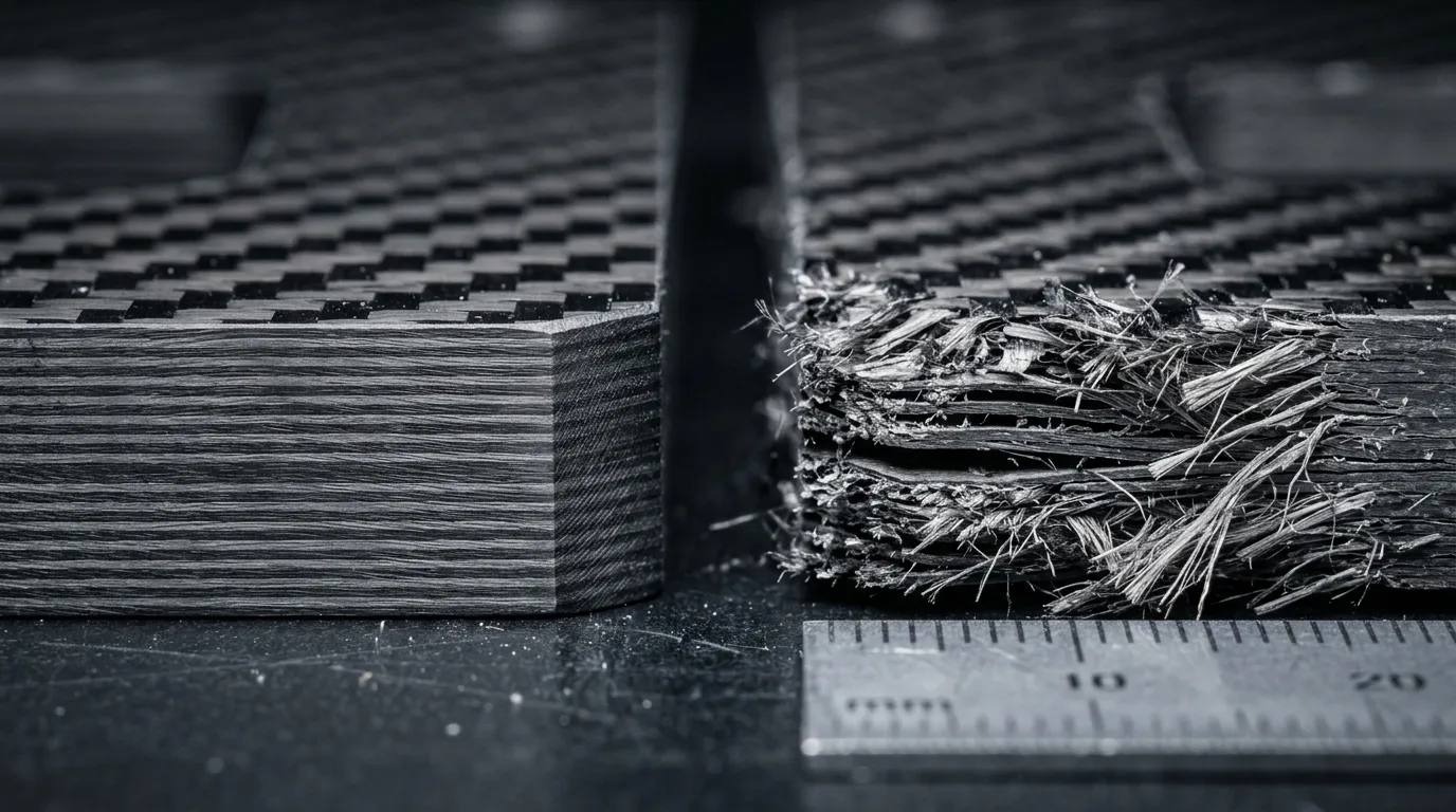
Why is machining composites different?
A carbon fiber laminate consists of hard fibers and a polymer matrix that behaves quite differently. As the cutting tool advances, the angle at which it meets the fibers and the ply structure can change. That is why a tool or cutting approach that works well for metals may not give the same result in a composite.
When evaluating machining, edge condition should be examined alongside dimensions. While the outer contour appears within tolerance, there may be lifting of surface plies, uncut fibers or internal separation. The significance of these defects depends on the function of the area and its load case. Appearance, dimensions and structural suitability are separate inspection topics.
How does delamination occur?
Delamination is the separation between plies of a laminate. It can occur when forces generated during machining push the plies apart. Hole exits and edges without adequate support need particular attention in this respect. When there is no backing material behind the last plies, the same process condition can give a different result.
Tool geometry, wear, feed, cutting speed and fixturing are evaluated together. Cutter geometries designed for composites can help limit delamination, but choosing the right tool alone does not eliminate every problem. The material's ply structure and the machine setup are also part of the outcome.
Why do part support and cutting sequence matter?
A thin plate can move under cutting forces. This movement can cause both dimensional deviation and local damage. The fixture must hold the part firmly without crushing or marking the surface at clamping points. With vacuum fixturing, how the held area and the seal change as the cut progresses must be taken into account.
The cutting sequence also affects the support arrangement. Opening large cutouts or the outer contour too early can reduce the support needed when machining later holes. Solutions such as temporary tabs or a backing plate are evaluated according to the shape of the part. Finishing of areas separated afterwards should also be included in the inspection plan.
Holes and countersinks are evaluated against assembly loads
For a hole, having the correct diameter is not enough. Position, roundness, entry and exit surfaces and the condition of the surrounding laminate should be checked. In structures where several parts are stacked and fastened, tolerance stack-up can cause forced assembly.
A countersink lets the fastener sit flush with the surface, but it also changes the local section by removing material. Cutting a deep countersink in a thin plate may not leave enough load-carrying plies around the joint. Countersink angle, depth and screw selection should be defined as design requirements, not decided by habit during assembly.
Tool wear and process control
Because of the abrasive effect of carbon fiber, tool condition can change over time. Good edge quality on the first part does not guarantee the same result throughout production. Tool life should be managed according to the accepted edge and hole quality, not only by the moment a tool breaks.
Cutting conditions are set from the tool manufacturer's recommendations, the material and sample results. It is not correct to give a single speed and feed value for every plate. Heat, vibration and chip evacuation should also be monitored. Proper collection of fine dust is part of the process, protecting the work environment, electronics and equipment.
At Tulkas, plate and machining are handled together
In Tulkas's approach to carbon plates and CNC-cut FPV frames, material selection and part geometry are evaluated together. When critical edges, holes and mating surfaces are defined on the drawing, the production and inspection scope becomes clear. The aim is a part that is not only cut to the right shape but also suits its intended assembly.
Frequently Asked Questions
Can carbon fiber be machined with an ordinary metal end mill?
Some tools can remove material under certain conditions, but suitability must be verified for edge quality, tool life and damage. Metal machining parameters should not be transferred directly without choosing a composite-appropriate geometry and cutting conditions.
Can delamination be removed by sanding?
Cleaning up a protrusion on the surface does not mean the separation between plies has been repaired. The extent of the damage and the function of the part should be evaluated. Rework or repair should only be carried out with a defined acceptance and repair approach.
Is a hole acceptable if its dimensions are correct?
Besides diameter and position accuracy, damage around the hole and the assembly requirement should also be checked. In load-bearing joints in particular, fiber breakage or ply separation can matter even when the dimensions are within tolerance.
Can the same CNC program be used on different carbon plates?
Even if the geometry is the same, machining behavior can change when the ply structure, resin or thickness changes. The program's tooling, feed, fixturing and inspection steps should be verified with the new material. Simply opening the file does not constitute production approval.
Let's evaluate the part to be machined together
Share your drawing, plate definition and critical holes and edges with Tulkas. Let's handle material, CNC cutting and assembly requirements within the same production plan.